
llama2-chatbot-cpu
A LLaMA2-7b chatbot with memory running on CPU, and optimized using smooth quantization, 4-bit quantization or Intel® Extension For PyTorch with bfloat16.
- 15
- Python
- MIT
- 3 y ago
Reusable 4-bit CPU in Logisim with Verilog HDL, ISA docs, and a browser playground
Repo SimDaSong/4-bit-cpu, read from GitHub 3 d ago. SimDaSong has not joined Take My Repo.
SimDaSong/4-bit-cpu is a public repo on GitHub by SimDaSong. Reusable 4-bit CPU in Logisim with Verilog HDL, ISA docs, and a browser playground. It declares no license on GitHub. Public does not mean open source: without a license, nobody is granted the right to reuse it. It is written mainly in Verilog, has 15 stars and last changed on 2026-02-24. Nobody has reviewed it on Take My Repo yet, which says nothing about its quality. Read from GitHub on 2026-11-20.
A fully functional 4-bit CPU designed from scratch using Logisim (visual circuit) and Verilog HDL (simulation).
Try it in your browser — write assembly, assemble, and step through execution with no install required.
This project was inspired by a circuit from Electronics Stack Exchange. The original circuit had issues when replicated, so it was fixed and improved. The instruction set and instruction decoder mapping were designed independently.
The CPU follows a single-cycle design — each instruction completes in one clock cycle.
graph LR
    INS["16-bit Instruction"] --> DEC["Instruction<br/>Decoder"]
    DEC -- "Control Signals<br/>(SUB, AFS, RSS, DWE, WE)" --> MUX["4-to-1<br/>MUX"]
    INS -- "Data (imm)" --> MUX
    MUX -- "Write Data" --> REG["3-Port Register File<br/>(8 × 4-bit)"]
    INS -- "Addr D, A, B" --> REG
    REG -- "A" --> ALU["ALU<br/>XOR / AND / OR<br/>ADD / SUB"]
    REG -- "B" --> ALU
    ALU -- "ALU Result" --> MUX
    REG -- "A (passthrough)" --> MUX
| Component | Description |
|---|---|
| Instruction Decoder | Decodes 4-bit opcode into 7-bit control signals (SUB, AFS, RSS, DWE, WE) |
| 3-Port Register File | 8 general-purpose 4-bit registers (R0–R7), 2 read ports + 1 write port |
| ALU | 4 operations — XOR, AND, OR, ADD/SUB (two's complement subtraction) |
| 4-to-1 MUX | Selects write-back source: immediate data, ALU result, or register value |
| 8-to-1 MUX | Selects register output for read ports |
| 3-to-8 Decoder | Converts register address to one-hot enable signal |
16-bit instruction format:
[15:12]  [11]  [10:8]  [7]  [6:4]  [3]  [2:0]
opcode    -    Addr D   -   Addr A   -   Addr B / Data
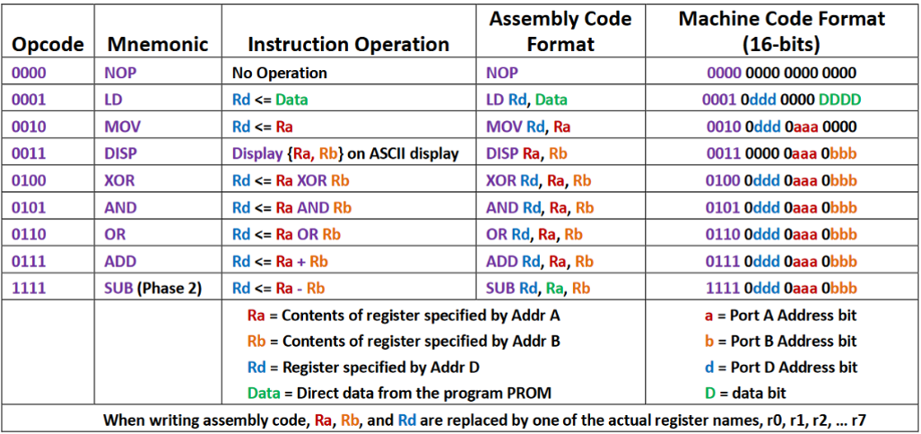
| Opcode | Mnemonic | Operation | Assembly Format | Machine Code |
|---|---|---|---|---|
0000 |
NOP | No operation | NOP |
0000 0000 0000 0000 |
0001 |
LD | Rd ← Data | LD Rd, Data |
0001 0ddd 0000 Data |
0010 |
MOV | Rd ← Ra | MOV Rd, Ra |
0010 0ddd 0aaa 0000 |
0011 |
DISP | Display (Ra, Rb) on ASCII display | DISP Ra, Rb |
0011 0000 0aaa 0bbb |
0100 |
XOR | Rd ← Ra XOR Rb | XOR Rd, Ra, Rb |
0100 0ddd 0aaa 0bbb |
0101 |
AND | Rd ← Ra AND Rb | AND Rd, Ra, Rb |
0101 0ddd 0aaa 0bbb |
0110 |
OR | Rd ← Ra OR Rb | OR Rd, Ra, Rb |
0110 0ddd 0aaa 0bbb |
0111 |
ADD | Rd ← Ra + Rb | ADD Rd, Ra, Rb |
0111 0ddd 0aaa 0bbb |
1111 |
SUB | Rd ← Ra - Rb | SUB Rd, Ra, Rb |
1111 0ddd 0aaa 0bbb |
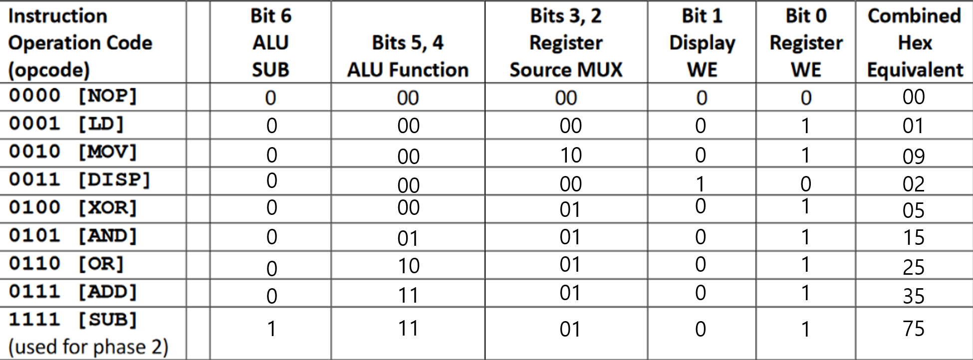
Each opcode maps to a 7-bit control word:
| Bit | Signal | Description |
|---|---|---|
| 6 | SUB | ALU subtraction flag |
| 5:4 | AFS | ALU function select (00=XOR, 01=AND, 10=OR, 11=ADD/SUB) |
| 3:2 | RSS | Register source MUX select |
| 1 | DWE | Display write enable |
| 0 | WE | Register write enable |
├── src/                      # Verilog HDL source
│   ├── cpu.v                 #   CPU top module (instruction decoder + datapath)
│   ├── alu.v                 #   Arithmetic Logic Unit
│   ├── three_port_reg_file.v #   8 x 4-bit register file with 3 ports
│   ├── cpu_tb.v              #   Testbench with sample program
│   ├── mux_4to1.v            #   4-to-1 multiplexer
│   ├── mux_8to1.v            #   8-to-1 multiplexer
│   ├── decoder_3to8.v        #   3-to-8 one-hot decoder
│   ├── fulladder.v           #   Full adder
│   └── Instruction.txt       #   Sample program listing
├── logisim/
│   └── 4-bit-cpu.circ        # Logisim circuit file
├── docs/                     # Web Playground (GitHub Pages)
│   ├── index.html
│   ├── style.css
│   └── cpu.js
├── images/
│   ├── Instruction-Set.png
│   ├── Instruction-Operation-Code(opcode).png
│   ├── logisim_main.png
│   └── verilog_cpu_tb.png
├── Makefile                  # Build automation (make run / make wave / make clean)
└── Dockerfile                # Run simulation without local install
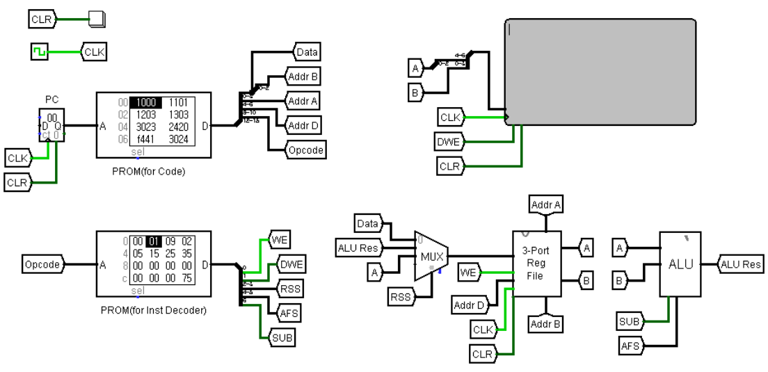
The Logisim implementation includes a Program Counter (PC) and two PROMs — one storing the program (instruction codes) and one storing the instruction decoder mapping. This makes it a fully self-contained, clock-driven CPU.
https://simdasong.github.io/4-bit-cpu/
Write assembly in the browser, assemble, and step through execution. Registers, program counter, and display output update in real time.
Requires Icarus Verilog and optionally GTKWave.
make run     # Compile and run simulation
make wave    # Compile, run, and open waveform viewer
make clean   # Remove build artifacts
docker build -t 4bit-cpu .
docker run --rm 4bit-cpu
The testbench (cpu_tb.v) runs the following program:
LD  $0, 0           # R0 = 0          (0x1000)
LD  $1, 1           # R1 = 1          (0x1101)
LD  $2, 3           # R2 = 3          (0x1203)
LD  $3, 3           # R3 = 3          (0x1303)
DISP $2, $3         # Display R3 → 3  (0x3023)
MOV $4, $2          # R4 = R2 = 3     (0x2420)
SUB $4, $4, $1      # R4 = 3 - 1 = 2  (0xF441)
DISP $2, $4         # Display R4 → 2  (0x3024)
ADD $3, $3, $1      # R3 = 3 + 1 = 4  (0x7331)
DISP $2, $3         # Display R3 → 4  (0x3023)
XOR $5, $3, $4      # R5 = 4 ^ 2 = 6  (0x4534)
DISP $2, $5         # Display R5 → 6  (0x3025)
AND $5, $3, $4      # R5 = 4 & 2 = 0  (0x5534)
DISP $2, $5         # Display R5 → 0  (0x3025)
OR  $5, $3, $4      # R5 = 4 | 2 = 6  (0x6534)
DISP $2, $5         # Display R5 → 6  (0x3025)
Expected display output: 3, 2, 4, 6, 0, 6

MIT
SimDaSong/4-bit-cpu is a public repo on GitHub by SimDaSong. Reusable 4-bit CPU in Logisim with Verilog HDL, ISA docs, and a browser playground.
It declares no license on GitHub. Public does not mean open source: without a license, nobody is granted the right to reuse it.
Its maker tagged it for macOS, Windows and Linux, or as Docker or cross-platform. That is declared by the maker; Take My Repo has not tested it.
Open "Take it" on its page: Take My Repo writes an install plan for your machine and hands it to your AI agent (Claude Code, Codex or Cursor), which asks you before each step. Take My Repo has not tested it on any machine.
Its last change on GitHub was on 2026-02-24. GitHub counts 0 open issues and pull requests. Take My Repo does not judge from that whether it is maintained.
A LLaMA2-7b chatbot with memory running on CPU, and optimized using smooth quantization, 4-bit quantization or Intel® Extension For PyTorch with bfloat16.
Nobody has reviewed it on Take My Repo yet, which says nothing about its quality.
RZ80: let's make new Z80 implementation C/FPGA/ASIC. Based on reverse engineering, schematics and chip die shots!


